Comprehensive Guide to RAM Pumps
29 October 2024
RAM Pumps Technology
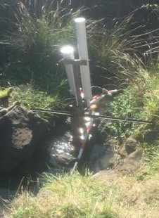
RAM pumps have been used for over two centuries to move water in areas that lack reliable power sources such as electricity and fuel-powered systems. These pumps harness the natural energy of flowing water from streams or elevated ponds to pump a portion of that water uphill.
RAM pumps are simple and low-cost devices that use water pressure to pump water uphill. This guide covers site evaluation, design, construction, tuning, and maintenance instructions in a step-by-step process for building and using RAM pumps.
Key Components of a RAM Pump
Details of all components are in this section.
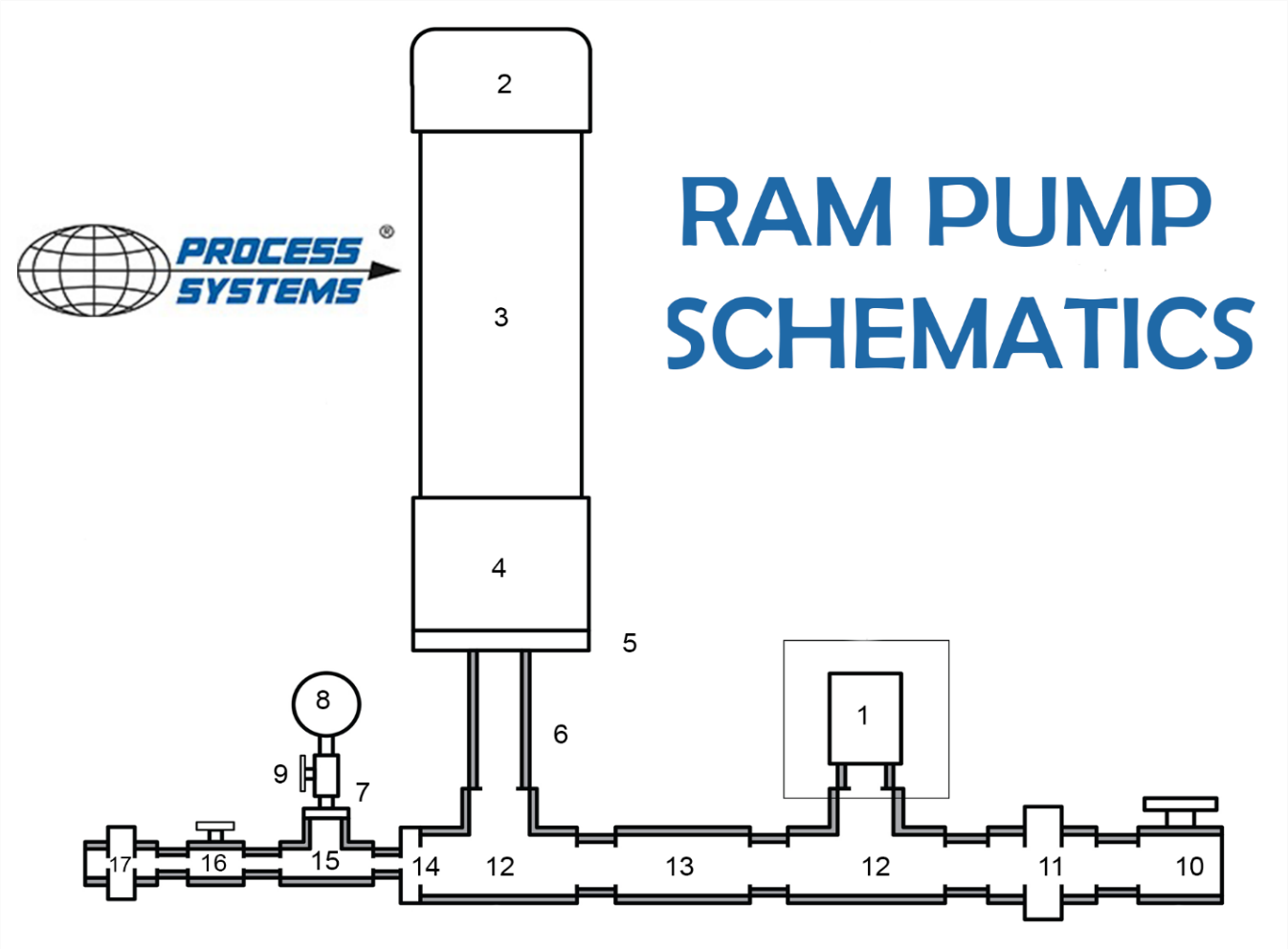
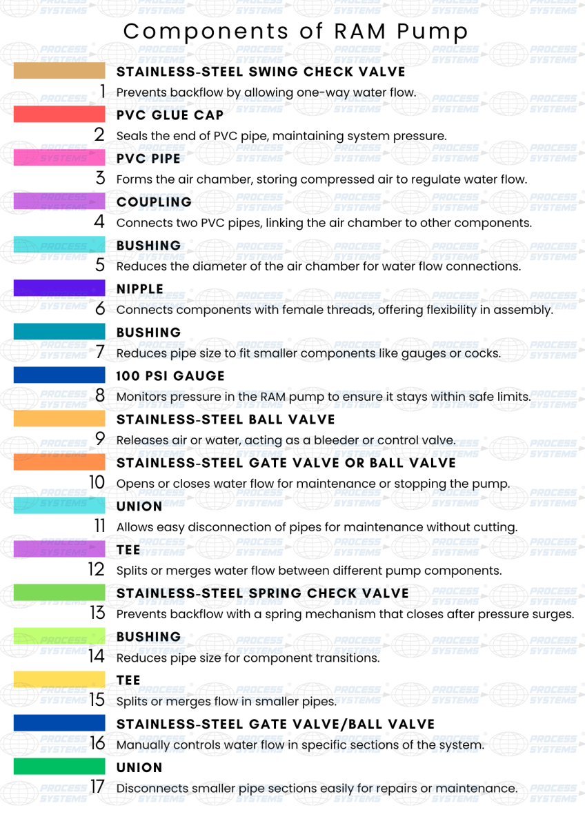
Water from the source flows through the drive pipe, building pressure as it reaches the stainless-steel spring check valve known as the waste valve. The Stainless-steel swing check valve and spring check valves control the direction of flow, preventing backflow during each pumping cycle. The air chamber, made of a PVC pipe capped with a glue cap, stores compressed air to regulate water flow by evening out pressure surges. Tees, unions, and bushings connect the system's sections, allowing water to transition between different pipe sizes for smooth operation. The pressure gauge and pipe cock monitor and release excess pressure or air, ensuring a safe and efficient system.
|
1 |
Stainless-Steel Swing Check Valve |
10 |
Stainless-Steel Gate Valve |
|
2 |
PVC Glue Cap |
11 |
Union |
|
3 |
PVC Pipe |
12 |
Tee |
|
4 |
Coupling |
13 |
Stainless-Steel Spring Check Valve |
|
5 |
Bushing |
14 |
Bushing |
|
6 |
Nipple |
15 |
Tee |
|
7 |
Bushing |
16 |
Stainless-Steel Globe Valve |
|
8 |
100 PSI Gauge |
17 |
Union |
|
9 |
Stainless-Steel 2-Way Ball Valve |
|
|
Specifically, the pressure gauge and its associated parts aren’t essential for the pump to function properly. If you exclude these parts, it can help reduce costs. You can still include them if you want, but they aren’t strictly needed for most setups.
Operational Mechanism of a RAM Pump
Now that you have learned what components are used in the construction of a RAM Pump, we can jump into its operational mechanism. Don’t worry if you do not understand the technical terminologies, we have covered it in detail in the following section.
RAM pumps offer a sustainable way to move water uphill without relying on external power sources as mentioned previously. Their simple mechanical design, with only two moving parts, ensures reliable operation and minimal maintenance.
The magic behind a RAM pump lies in harnessing the natural force of water flowing downhill—gravity at work. This is similar to how hydropower stations generate energy, but the RAM pump takes a different approach. Instead of relying on the pressure of water, it uses the momentum, or inertia, of moving water to operate in a cycle.
So how does this process unfold? Here’s a closer look:
- When the stainless-steel spring check valve (waste valve) opens, water begins flowing from the source, down through the inlet (also called the drive pipe), and exits through the waste valve.
- As the water picks up speed, its velocity reaches a point where it forces the waste valve to shut. But water doesn’t just stop—it keeps moving forward, using its inertia to create a pressure spike inside the pump (also known as water hammer).
- This pressure is enough to open the stainless-steel spring check valve, which allows some of the water to enter the pressure vessel. Inside, the water compresses an air bubble, and this stored energy is then used to push water through the delivery pipe to its destination.
Imagine a RAM pump cycling 60 times per minute, delivering about 20 litres per minute, or roughly 29,000 litres each day. With each cycle, around 330 ml of water is moved. The air inside the pressure vessel helps smooth out the water flow, so instead of small bursts with each cycle, it becomes a steadier stream.
This seamless interaction between the waste valve, check valve, and pressure vessel keeps the pump running efficiently, without external power—just the sheer force of water and gravity working together.
When the check valve opens, the built-up pressure from the closing waste valve gradually dissipates. At this moment, the water attempts to reverse its course, but the check valve quickly shuts, blocking any backflow.
As the pressure in the drive pipe drops, the waste valve reopens, allowing water from the source to rush back into the system. This triggers a fresh cycle, repeating itself up to 120 times a minute, depending on the pump’s setup—its size, the height of the water lift, and the flow rate. Each piece of the system works in harmony, creating a continuous cycle of water movement.
Pre-Installation Guide
Without any further delay, let us move to the construction of the RAM Pump. It doesn’t start from enjoining the components but there are some pre-requisites to understand before the construction of the RAM Pump. The key steps are as follows:
Site Assessment
The first step is a thorough site assessment. It involves:
Water Source
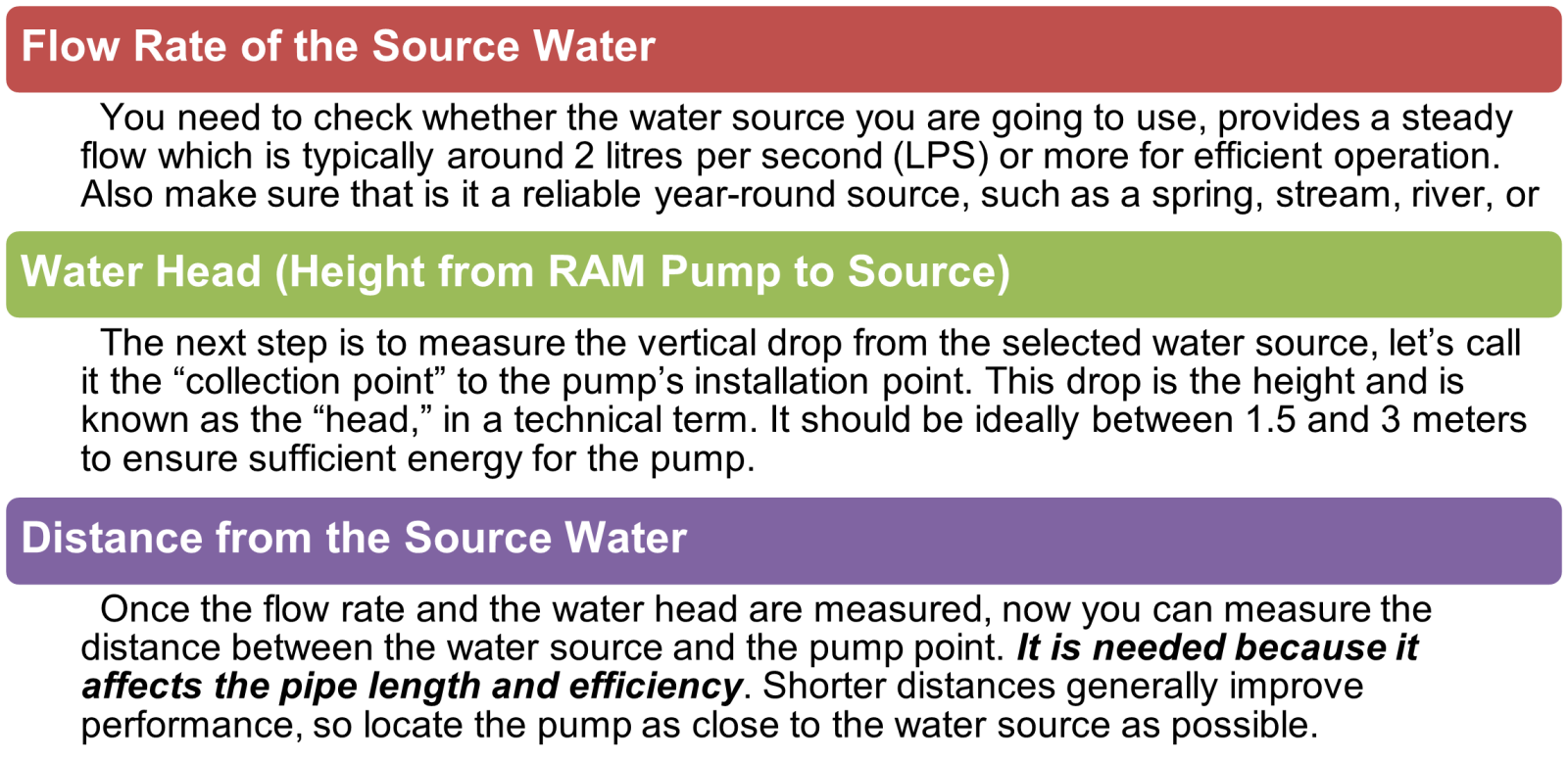
Delivery Point Elevation
Identify the final destination of the pumped water. The RAM pump can typically lift water to an elevation 7 to 10 times the height of the head. Ensure that the lift requirement is within the pump’s capacity.
Delivery Point Distance
Measure the horizontal distance from the pump to the delivery point. Long distances will require additional piping and may affect water pressure and efficiency.
Environmental Considerations
Before setting RAM Pump, you can think of setting up a pump-like building on firm ground for a house. First, you will make sure the ground is stable, flat and secure enough to hold the pump and any structures. Just like protecting a yard from washing away, put measures in place to stop soil erosion, especially if there's a lot of water or rain nearby. Now, think about easy access. Place the pump where you can reach it for repairs, not in a tricky spot. To keep it running smoothly, it's like putting a screen door on a house—add a filter to stop leaves and sticks from getting in and clogging it.
Hydraulic Considerations
For setting up the drive pipe, think of it like a slide—it needs a smooth, consistent downhill slope from the water source to the pump. Any dips or bends, like bumps in the slide, can trap air and slow down the water flow, making the system less efficient. Keeping the path clear and steady ensures the water moves smoothly.
Just like choosing the right size hose for a garden, the pipe size needs to fit the pump’s inlet to work well. If the pipe is too small, water struggles to flow; if it's too large, pressure doesn’t build up as efficiently. The air chamber, acting like a buffer zone, should be sized right, too. A larger chamber helps even out water flow, especially for pumps that need to lift water higher or send it over long distances.
Pre-Assembly Preparation
To calculate the length of the drive pipe, it's important to strike the right balance. A longer pipe can increase the force driving the pump, but if it's too long, friction will slow the water down. Make sure the pipe is just the right length to deliver power without losing efficiency.
Before committing to the full installation, do a dry run to test everything. Check all the valves, pressure chamber, and waste valve to ensure they're all working properly, and look out for any leaks. Safety comes first, so always wear gloves and safety glasses when handling pipes or chemicals. And don’t forget to mark areas for digging, making sure you're clear of any buried utilities like power or water lines.
Construction and Installation of RAM Pump
Review these instructions carefully to familiarize yourself. You need to make a list of components that we have provided above – these are required to construct the RAM Pump. You can choose the right dimension based on the availability of the component and simply visit the Process Systems Online Store to get everything delivered to your doorstep. You only need to understand functions, so you can find a replacement to the required one, that can fit neatly and correctly in overall fittings. You can be creative here and modify the initial design considerations.
Step-01 Material and Tools
We have comprehensively covered the essential list of components or simply say Bill of Material in the above section. That is step 1; to gather all the components, tools and materials. Along with essential components, there are some pump assembly tools that you need such as below”. Also it is worth noting that these RAM pumps can be made of other materials such as steel however they are more difficult to build as a DIY as they require a good level of welding especially for the pressure vessel.
Build Materials and Tools
These are some of the tools and additional materials that will either be already in your home store or you can get along with items from an online store.
- Hacksaw (to cut the PVC pipes)
- PVC Primer (Optional)
- PVC Adhesive (for better fixing of the joint)
- Plumber’s Tape (To seal connections)
- Inch Tape (to measure the length and for dimension)
- Steel Clamps to fix the connections
- Sand Paper Sheet to make the cuttings smooth
- Industrial Gloves (to prevent chemicals from contacting your hands)
- Air Pump (for inflating the inner tube)
Step-02 Layout of the Material of RAM Pump
All right, let's get this assembly process started! Now that you've got your hands on all those pump parts, spread them out on the table (or floor) like a treasure map. It's time to piece together this pumping puzzle! Take a peek at the schematic image as shown above in the component section along with a numerically marked table. You will need to cut the long pipes into shorter sections to fit between the fittings. Once you have understood the layout, it will be easy to build and connect the components.
Don't worry, we'll cover that in more detail next.
Step-03: Cutting Connecting Pipe Pieces
Pipes are the most important pieces used in RAM Pump construction. So, now, let's get those pipes ready to connect your units. Using your hacksaw, cut segments of pipe according to your calculated dimensions. Do not cut the longer pieces as it is only required to get into the fittings only. You can guess the size after seeing the fitting and how much length is required.
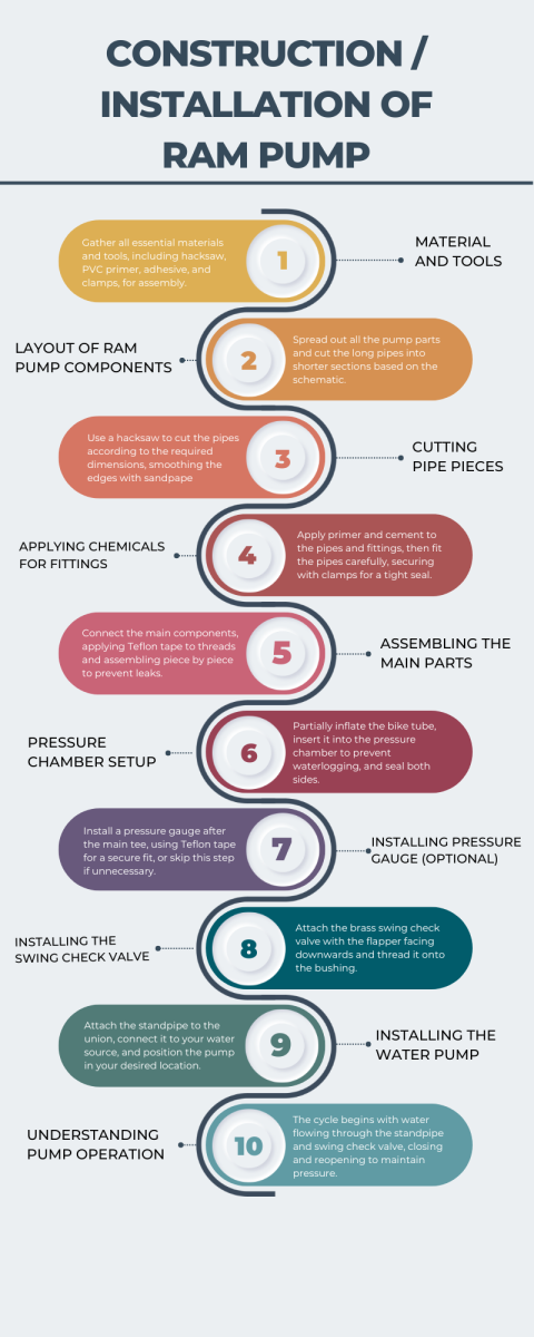
Once you have cut these, use sandpaper to smooth the inside edges of the pipe. Also, try to remove any burrs and create a nice bevel or a rounded edge. This will help prevent cracks from forming due to the pressure waves. Do this at the end of each pipe piece and prepare them to join.
Repeat the same sanding process on all the pieces that you cut. Once you are done with all, the pipe pieces are ready for fitting. Before applying any adhesive or Teflon tape, try to test fit them and make sure they are ready for final fittings. Wait, while we are not going to join them at this stage. So, let's move to step 4.
Step-04: Applying Chemicals for Fittings
Here in step-04, you can now head to an open area where the air crossing is good. Because the chemicals you will be applying do have not so good smell. So, get your equipment and chemicals with you and let's start the fitting process.
If you're new to PVC construction, don't worry, it's not rocket science. The primer cleans the PVC and prepares it for a strong bond with the cement, while the cement acts as the glue. If you do not find the complimentary brush, you can grab one from the store. However, it is present with the caps to apply.
Without staining any undesired surfaces, you can now apply the primer on the ends of the pipe. After priming the pipe, now prime the other fittings in which you are going to fit the pipes. Once the priming is done, now you will need to apply the cement which will work as glue. Apply a coat of cement to the primed areas on all pieces. Do not take much time because the cement will dry up quickly. This also doesn't mean to be hasty, that is why be efficient but do not be quick to ruin the pieces.
With the presence of cement, carefully fit the pipe into the fitting. It should have been done with minimal resistance. We recommend you use clamps on each piece after assembly. It will prevent the pipe from slipping back. You may not clamp but it is merely a recommendation because this will make sure an error-free fitting, so it will be helpful.
Pipe fitting is a simple process that needs no attention to detail, but valve fitting is not the same. The two important valves; the stainless-steel spring check valve and the stainless-less steel swing check valve have markings of arrows to tell the direction of flow. You need to point the spring check valve to the main tee as shown in the schematics above. This allows water to flow towards the main tee. Moreover, the arrow of the swing check valve should point downwards towards the tee and the main pipe as shown in the figure above.
Now is the most important step of constructing a RAM pump, which assembling the main line.
Step-05: Assembling the main part-Piece by Piece
In this step you need Teflon tape, so get it ready. Start by connecting the valve to the union. You can choose your starting point, but assembling the main line first provides a stable base for clamping. Attach the bushing to the tee. Once the bushing is in position, the end assembly should be glued separately before being connected to the main assembly with the threaded pipe. Wrapping Teflon tape around the threads will help prevent leaks and ensure smooth operation when the sections are joined.
Step 6: Pressure Chamber Setup
Now you will partially inflate the bike tube using the pump. Make sure to not over-inflate the tube. It needs to be slightly squishy because it will act as a spring within the pressure chamber. This tube works as an anti-blockage unit for the chamber, so that it might not get waterlogged during working.
It is a general principle that at high pressure, air dissolves into water quickly and clogs the chamber. The use of a bike tube prevents this from happening by requesting the air and pushing it out of the pressure chamber. This ensures the smooth operation of the RAM pump. What you need to do is, put this tube as shown in the RAM pump schematics above and enclose both sides with cement. Let it dry. Once it is ready, you can install it into the main system.
If you are not comfortable with this process of using the bike tube, you can skip this. In this case, you will need to drain the pump periodically so that the air entrapped inside may leave the chamber. You can choose the most feasible option for you as there is no hard and fast rule to use one and leave the other.
Step 7: Installing Pressure Gauge (It is Optional)
Using a pressure gauge is beneficial as it will tell you about the current pressure of the pressure chamber. If you don’t want to use it, you can skip this step. It is just a suggested step not a recommended or inevitable one.
So, if you have decided to install a pressure gauge, you have to install it after the main tee. Just follow the instructions to install the pressure gauge that comes with it or simply check the illustration above that is schematically showing the position and components of the gauge assembly. It is simple and easy to set up gauge but to eliminate the chances of error, you can follow the instructions carefully. Do use Teflon tape to fit the assembly here and tighten the connections securely.
Step 8: The Final Piece
First, install the stainless-steel swing check valve (you can also use Brass if you want however stainless has a better level of corrosion resistance) if you haven't done so already. As you hold the pump upright, ensure that the flapper is positioned facing downwards. The valve should thread securely onto the bushing you’ve cemented at the pipe’s end. Double-check that everything is aligned properly for a tight seal and smooth operation.
Congratulations! You've successfully completed your pump. Now, you can kick back, relax, and enjoy the fruits of your labour.
Step 9: Installing Your Homemade Water Pump
Now that you've assembled your DIY water pump, it's time to put it to work!
You can begin by attaching the standpipe to the union using cement. You are free to decide how you want to connect the other end to your water source. We recommend mounting something to drain on the end of the standpipe and securing it.
Now you can gather your garden hose, standpipe, and pump, and take them to your desired location, such as a waterfall. Bring along a friend or two to help with setup and perhaps even join you in a friendly wager about the pump's capabilities.
In a nutshell, connect the standpipe to the main pump, then allow water to flow down the standpipe and up through the swing check valve. Avoid areas prone to flooding or debris. Also, consider seasonal factors. In colder climates, water can freeze inside the pressure chamber, causing damage.
Step 10: Understanding the Pump's Operation
When the pump cycle begins, water first flows down through the standpipe and then moves upward through the swing check valve. As the water’s velocity increases, friction causes the flapper in the valve to lift, closing the valve. This sudden closure creates a pressure spike inside the pump body because the descending water has no outlet.
To relieve this pressure, some of the water flows through the spring check valve and into the pressure chamber. The spring check valve’s design prevents the water from flowing back once it has passed through.
As the pressure difference across the spring check valve decreases, the valve closes, stopping the water flow. This lower pressure then allows the swing check valve to reopen, beginning the cycle again.
Troubleshooting
Occasionally, you might notice water flowing out of the swing check valve, only for it to shut abruptly without restarting the cycle. If that happens, try gently tapping the flapper to release it and allow the cycle to resume. Although these pumps typically require back pressure from the pressure tank to function, a little tapping and minor adjustments are usually enough to get it running smoothly again.
Tuning Your Homemade Water Pump
One of the factors influencing the pump's effectiveness is the maximum height it can lift water. This height depends on various factors, including the source water head. You can find specific formulas online to calculate theoretical pumping heights. Some of the important tuning points are as chart below:
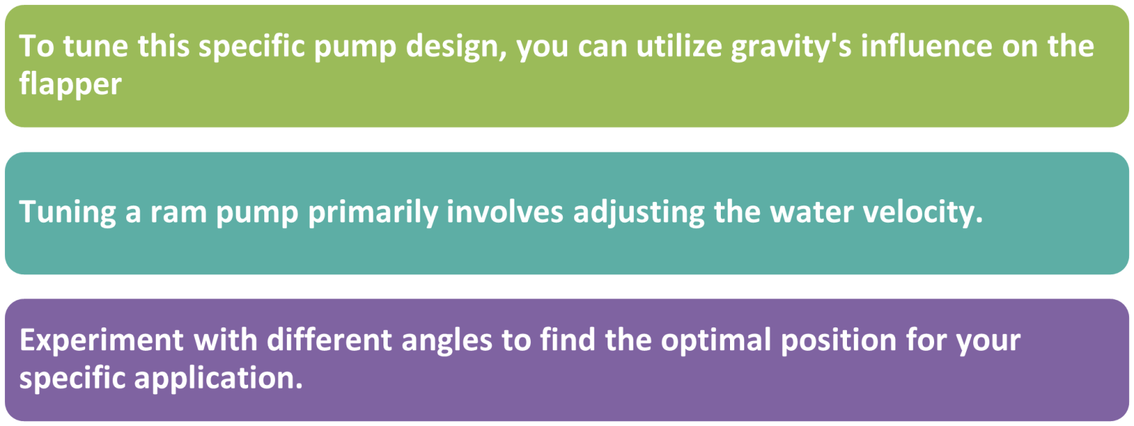
However, this also results in a slower cycle, reducing the overall pumping rate. Conversely, if the swing check valve closes at a lower water velocity, the pump cycles faster but here another issue arises that water cannot reach as high a pumping height.
Role of Valves in RAM Pump
Valves are the most important components of a RAM pump. The main types of valves that are used in the construction of a RAM pump are:
- 2-Way Stainless-steel ball valve (inlet and outlet point) or Gate Valves
- Stainless-steel swing check valve
- Stainless-steel spring check valve
- Ball Valve for Pressure Gauge (optional)
As you have learned valves play a critical role in the functioning of a RAM pump, as they control water flow, generate pressure, and enable the pumping action. If we learn about the functionality of the valve, the two primary valves involved in the RAM pump's operation are the waste valve and the check valve. Together, they create a self-sustaining cycle that harnesses the energy of flowing water to pump a portion of that water uphill, without the need for any external power source.
Waste Valve (Impulse Valve)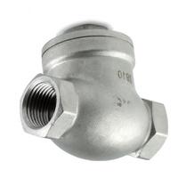
The waste valve is the key component that initiates and regulates the cycle of the RAM pump. It is usually in an open position, allowing water to flow through the drive pipe and escape from the pump.
Initial Water Flow
When the system begins, water flows freely from the source through the drive pipe and out of the open waste valve. As water flows, it picks up speed due to the downhill slope, gaining momentum.
Valve Closure
Once the water reaches a certain velocity, the pressure created by its flow forces the waste valve to slam shut. This sudden closure is essential for creating a pressure surge in the system, which powers the pump.
Cycle Control
The waste valve automatically reopens once the pressure inside the pump drops after the check valve closes. This reopening allows the next cycle of water to start flowing again.
The waste valve’s repeated opening and closing drives the cyclical action of the pump, enabling continuous water movement and pressure buildup.
Check Valve (Delivery Valve)
The check valve plays a crucial role in ensuring that water flows in only one direction—toward the delivery pipe—and preventing backflow into the system.
Pressure Surge Activation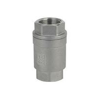
When the waste valve closes and a pressure surge builds up inside the pump, the check valve is forced open by this high pressure. This allows a portion of the water to be pushed through the check valve and into the delivery pipe, which leads to the higher elevation where the water is needed.
Prevents Backflow
After the pressure surge is released and the flow tries to reverse, the check valve automatically closes, preventing water from flowing backwards into the pump. This ensures that water continues to move uphill and remains in the delivery pipe.
By allowing water to flow forward during the pressure surge and preventing it from flowing backwards afterwards, the check valve plays a key role in maintaining the one-way flow of water in the system.
Potential Applications of RAM Pump
We hope you have installed the pump or are ready to order the components at least to start constructing your RAM Pump. Let us guide you about some of the applications of RAM Pumps. We know you know it all but still, if you want to learn a little more, let us take you through a quick review of the potential application of a RAM Pump.
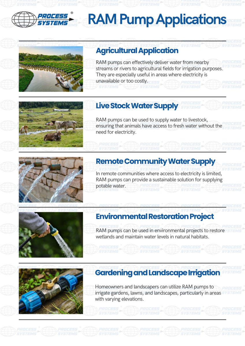
As you know, RAM pumps are versatile devices that can be used in a variety of applications where water needs to be lifted to higher elevations without electricity. The first application is agricultural irrigation in far-flung areas.
Why Choose a RAM Pump?
- Reduce operational costs with a system that requires no electricity and minimal maintenance.
- Harness the power of flowing water, promoting eco-friendly practices while providing a reliable water supply.
- Suitable for agricultural, livestock, community, environmental, and emergency use.
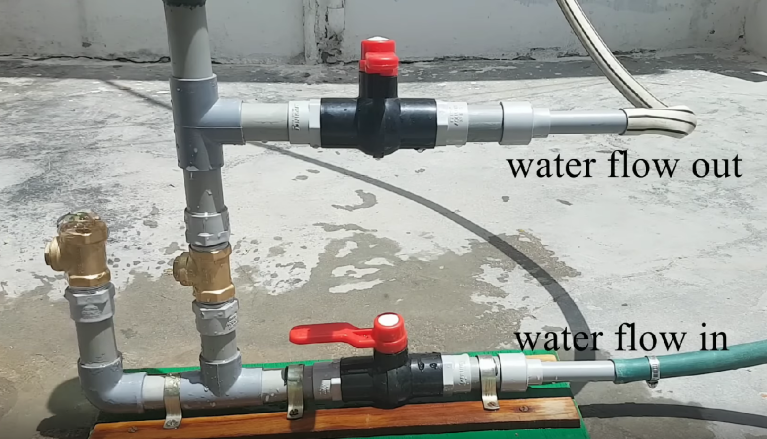
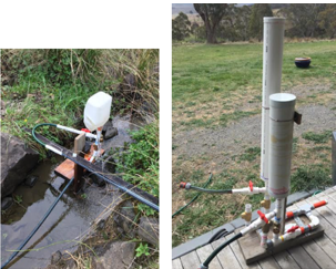
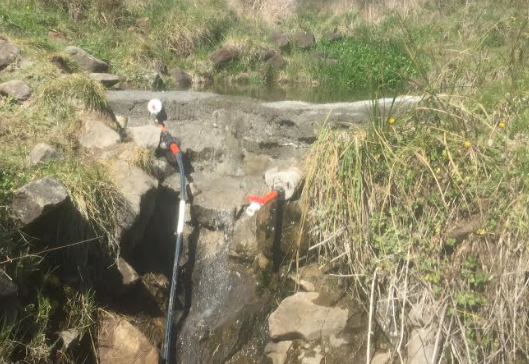
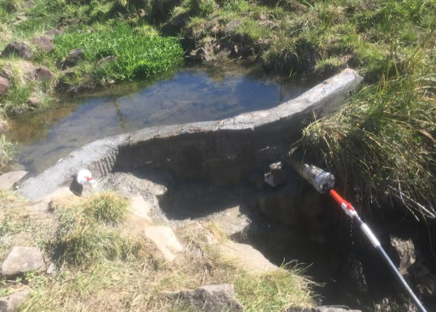
Our Customers Build Different RAM Pumps
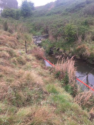
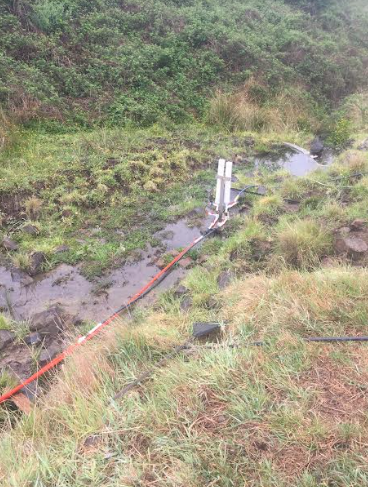
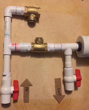
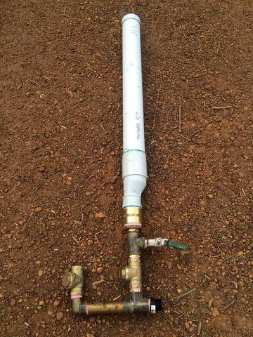
Following is some of the satisfied customers who built the RAM pump using our components.
|
|
|
|
|
|
|
|
|
|
|
|
By choosing a RAM pump, you invest in a reliable, cost-effective solution for your water lifting needs. Join the growing number of satisfied customers who have experienced the benefits of this innovative technology.
Final Words
No such pump exists that doesn't require external power but RAM Pump. It harnesses the potential energy of the uphill water source by strategically wasting a portion of the flowing water. While only a small fraction of the water is pumped, it's a valuable solution for situations where a stream is already flowing downhill. This allows you to utilize the existing potential and kinetic energy for practical purposes.
Recent Blogs
Date Posted: 21 November 2024
International Valve Leakage Testing StandardsDate Posted: 10 November 2024
Understanding Industrial Grade Stainless Stee
